
FLARM Connector Electrical Connections
The FLARM IN and FLARM OUT connectors are electrically connected internally inside the control box. This allows the FLARM connection to pass through the control box to another compatible device.
The Glider Canopy Flasher control box itself connects only to:
- GND; and
- the FLARM RS-232 TX line, which is used by the control box to receive FLARM data.
The control box does not connect to, generate or supply either the FLARM +3 V display supply or the +12 to +32 V power-supply lines.
FLARM +3 V Display Supply
The +3 V display supply is not available on all older FLARM devices. For this reason, the Glider Canopy Flasher does not use this line and does not feed it from its own internal 3.3 V supply.
This avoids applying voltage to a FLARM connector pin that may be unsupported, unused or electrically different on some equipment.
FLARM Power-Supply Lines
The +12 to +32 V lines on the FLARM connector are passed directly between the FLARM IN and FLARM OUT connectors. Any power present on these pins must be supplied by the connected FLARM equipment or aircraft installation.
The Glider Canopy Flasher has its own separate aircraft power connection and does not connect its power supply to the FLARM power pins. This prevents backfeeding between devices and reduces the risk of unwanted current paths or other electrical problems.
Important: the presence and permitted use of the +3 V and +12 to +32 V pins depend on the connected FLARM equipment. Always check the installation documentation for the specific FLARM device.
FLARM RJ45 Cable Pinout
The cable pin numbering and connections are shown in the technical drawing below.
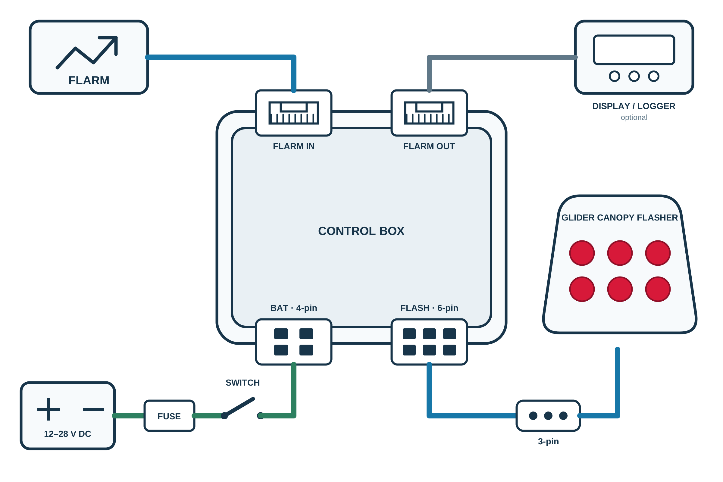
Electrical Connection Overview
The diagram above shows the recommended electrical connection of the Glider Canopy Flasher, its control box, the aircraft power supply and the FLARM data connection.
The FLARM data connection passes through the control box, allowing an existing FLARM display, navigation device or flight logger to remain connected. The canopy-mounted flasher is connected separately using the supplied flasher cable and detachable three-pin connector.
Power Supply Connection
Connect the control box to a suitable 12–28 V DC aircraft power supply through the BAT 4-pin connector.
- The power supply must be protected by a correctly rated fuse.
- An accessible switch should be installed so that the system can be isolated when required.
- The correct supply polarity must be observed.
- Use suitable cable and secure all wiring against movement, vibration and abrasion.
The fuse should be installed as close as reasonably possible to the point at which power is taken from the aircraft electrical system. The fuse and switch are shown separately in the diagram and must be selected and installed as part of the aircraft electrical installation.
Canopy Flasher Connection
Connect the supplied flasher cable to the FLASH 6-pin connector on the control box. The opposite end of the cable connects to the canopy-mounted Glider Canopy Flasher through the detachable three-pin connector.
The detachable three-pin connector allows the canopy-mounted flasher to be disconnected without removing the complete control-box wiring. The connector’s locking pin has been removed so that the connector can separate easily if the canopy is jettisoned.
Route and support the cable so that the connector cannot disconnect accidentally during normal operation, while remaining free to separate without restricting or delaying emergency canopy release.
Ensure that the connector is fully engaged during normal use and that the cable cannot be trapped, stretched or damaged when the canopy is opened or closed.
Only use the supplied cable or a cable manufactured to the specified Glider Canopy Flasher pinout. Do not assume that connectors with the same physical appearance use the same electrical connections.
FLARM Connection
Connect the FLARM device to the FLARM IN socket on the control box using the correct FLARM-compatible RJ45 cable.
The control box receives the FLARM serial data used to select the appropriate normal or collision-warning flash pattern. The FLARM data connection is also passed through to the FLARM OUT socket.
Optional Display or Logger
An existing FLARM display, navigation device or flight logger may be connected to the FLARM OUT socket. This allows the Glider Canopy Flasher control box to be installed between the FLARM device and the existing cockpit equipment.
The control box connects to the FLARM ground and receives the FLARM transmit data only. The FLARM IN and FLARM OUT connections are internally linked so that the required FLARM signals remain available to the connected display or logger.
The control box does not take power for the canopy flasher from the FLARM connector and does not supply the FLARM connector’s 12 V or 3 V power outputs. Any connected display or logger must be powered in accordance with its own manufacturer’s instructions.
Recommended Connection Sequence
- Switch off and isolate the aircraft electrical supply.
- Install the fuse and isolation switch in the positive supply connection.
- Connect the aircraft power cable to the BAT 4-pin connector.
- Connect the canopy flasher cable to the FLASH 6-pin connector.
- Connect the detachable three-pin connector to the canopy-mounted flasher.
- Confirm that the three-pin connector can separate freely without restricting canopy jettison.
- Connect the FLARM device to the FLARM IN socket.
- Where required, connect the existing display or logger to the FLARM OUT socket.
- Check every connection, cable route, connector orientation and wire polarity.
- Apply power and complete the functional test described in the commissioning instructions.
Important Wiring Warning
Incorrect wiring may damage the Glider Canopy Flasher, the FLARM device, connected displays, loggers or the aircraft electrical system.
Before making any connection, verify the pinout and electrical specification of the particular FLARM or other device being connected. FLARM-compatible connectors may carry both power and data signals, and their connections can differ between equipment manufacturers and models.
The installation must not interfere with the normal operation, opening or emergency jettisoning of the canopy. Check that the cable and three-pin connector separate freely during canopy release and cannot become caught on any part of the aircraft.
If there is any doubt about the aircraft wiring, connector pinout, power supply, fuse rating, cable routing, canopy-release arrangement or compatibility of the connected equipment, the installation must be checked by a suitably qualified person before power is applied.
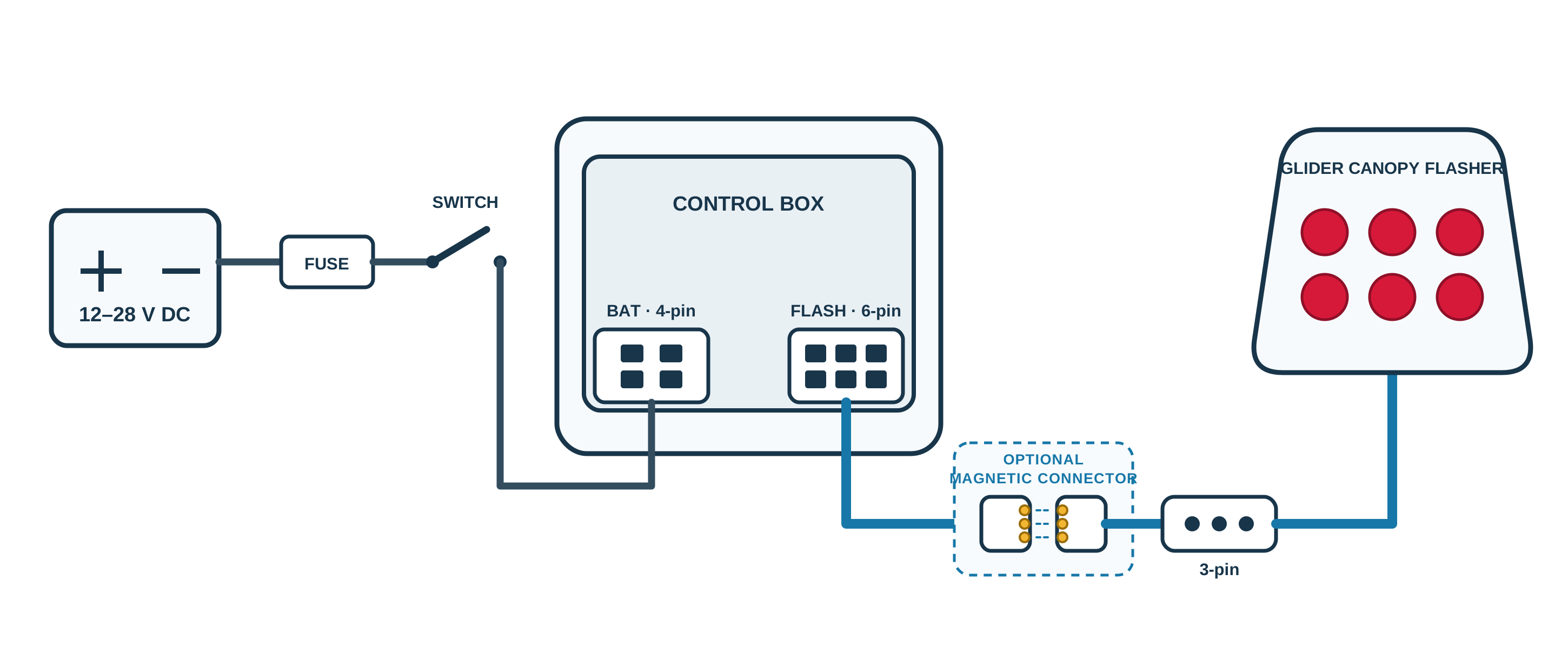
Optional Magnetic Connector
The optional magnetic connector is intended mainly for gliders with a side-opening canopy where the aircraft configuration does not provide a practical way to route the flasher cable directly between the control box and the canopy-mounted Glider Canopy Flasher.
One half of the magnetic connector is installed on the fixed part of the aircraft and the matching half is installed on the canopy. When the canopy is closed, the two halves align magnetically and complete the electrical connection to the flasher. When the canopy is opened or removed, the connector separates automatically without requiring the cable to be disconnected manually.
The connector must be positioned so that both halves meet naturally and remain correctly aligned when the canopy is fully closed. It must not be used to pull the canopy into position, support the cable or carry any mechanical load.
The cables on both sides of the connector must be secured while retaining enough freedom of movement for the connector to separate cleanly. The wiring must not become stretched, trapped or caught in the canopy hinges, locking mechanism or surrounding structure.
The magnetic connector must not interfere with normal canopy opening, removal or emergency jettison. Its position and cable routing must allow the two halves to separate freely whenever the canopy moves away from the aircraft.
The magnetic connector is not required where the glider configuration allows the supplied cable and detachable three-pin connector to be installed safely without it.
After installation, check that the connector aligns correctly and that the Glider Canopy Flasher operates reliably each time the canopy is closed. Repeat this check after any adjustment to the canopy, hinges, catches or cable routing.
Important Wiring Warning
Before connecting the Glider Canopy Flasher, always verify the pinout, voltage levels and signal assignments of the FLARM unit or any other connected equipment.
Do not assume that all devices use the same RJ45 wiring. Incorrect wiring may damage the Glider Canopy Flasher, the connected equipment or the aircraft electrical system.
If you are not completely certain that the wiring is correct, ask a suitably qualified person to inspect and verify the installation before power is applied.
We accept no responsibility for damage caused by incorrect wiring, unsuitable connections or failure to verify the connected equipment.