
Connecting to the Glider Canopy Flasher Wi-Fi (Click to expand)
Connecting to the Glider Canopy Flasher Wi-Fi
The Glider Canopy Flasher creates its own local Wi-Fi access point when the controller is switched on.
This network is used to open the configuration pages, test flash patterns and install firmware updates. It does not provide internet access.
Wi-Fi Network Name
The Wi-Fi network name uses the following format:
RTOIP-<serial number>
For example, a controller with the serial number:
FLR-A5C35B-EB
creates the Wi-Fi network:
RTOIP-FLR-A5C35B-EB
The serial number can therefore be read directly from the Wi-Fi network name displayed by the phone or computer.
Wi-Fi Password
The Wi-Fi password is the controller serial number without the RTOIP- prefix.
Using the example above:
- Wi-Fi network: RTOIP-FLR-A5C35B-EB
- Password: FLR-A5C35B-EB
Enter all letters, numbers and hyphens exactly as displayed.
The password is intentionally easy to obtain from the network name so that the pilot or installer does not need to find a separate password label while working in the cockpit.
The Glider Canopy Flasher network is a local configuration connection with limited range and normally remains available for only a short period after startup. It does not provide access to the internet or to the aircraft FLARM itself.
This makes the practical risk of unwanted access low during normal use, although it is not zero. Do not leave the configuration access point permanently enabled unless continuous Wi-Fi access is required.
Opening the Configuration Page
After connecting to the Glider Canopy Flasher Wi-Fi network, open a web browser and enter:
http://172.27.149.1
Enter the complete address, including http://.
The main Glider Canopy Flasher configuration page should then appear.
Connecting with an Android Phone or Tablet
- Switch on the Glider Canopy Flasher.
- Open Settings on the Android device.
- Open Network & internet, Connections or Wi-Fi. The exact name depends on the phone manufacturer.
- Turn Wi-Fi on.
- Wait for the list of available networks to appear.
- Select the network beginning with RTOIP-.
- Use the part after RTOIP- as the password.
- Press Connect.
- If Android reports that the network has no internet access, select an option such as Stay connected, Connect anyway or Use this network as is.
- Open Chrome or another browser.
- Enter http://172.27.149.1 in the address bar.
Android No-Internet Message
Android may display messages such as:
- No internet access;
- Connected without internet;
- This network has no internet;
- Internet may not be available.
This is normal. The Glider Canopy Flasher Wi-Fi network is used only for direct communication with the controller.
Choose the option that keeps the phone connected to the network.
If the phone repeatedly changes back to mobile data or another Wi-Fi network:
- temporarily disable mobile data;
- temporarily disable automatic network switching or adaptive connectivity;
- forget another nearby Wi-Fi network if the phone keeps reconnecting to it;
- reconnect to the RTOIP network and select the option to remain connected.
Connecting with an iPhone or iPad
- Switch on the Glider Canopy Flasher.
- Open the iPhone or iPad Settings app.
- Select Wi-Fi.
- Make sure Wi-Fi is switched on.
- Wait for the available networks to appear.
- Select the network beginning with RTOIP-.
- Use the part after RTOIP- as the password.
- Tap Join.
- Remain connected if the iPhone reports that the network has no internet connection.
- Open Safari.
- Enter http://172.27.149.1 in the address bar.
iPhone No-Internet Message
The iPhone may show No Internet Connection beneath the RTOIP network name. This is expected and does not indicate a fault.
The phone is communicating directly with the Glider Canopy Flasher rather than connecting through it to the internet.
If Safari does not open the configuration page:
- confirm that the RTOIP network remains selected;
- temporarily turn off mobile data;
- temporarily disable any VPN service;
- close and reopen Safari;
- enter the full address http://172.27.149.1.
Connecting with a Windows 11 Computer
- Switch on the Glider Canopy Flasher.
- Click the network, sound and battery area on the right side of the Windows taskbar.
- Click the arrow beside the Wi-Fi button to display available networks.
- Select the network beginning with RTOIP-.
- Click Connect.
- Enter the part after RTOIP- as the network password.
- Click Next.
- Open Microsoft Edge, Chrome, Firefox or another web browser.
- Enter http://172.27.149.1 in the address bar.
Windows No-Internet Message
Windows may display the RTOIP connection as:
No internet, secured
This is normal. The Wi-Fi connection is secured and is working locally, but it does not provide internet access.
Do not disconnect from the RTOIP network merely because Windows displays the no-internet message.
Configuration Access-Point Time
The configuration Wi-Fi access point normally remains available for approximately 120 seconds after the controller starts.
The timer runs only while no Wi-Fi device is connected. Once a phone, tablet or computer connects, the access point remains active while that device stays connected.
After the final device disconnects, the configured timer starts again.
If the RTOIP network is not visible:
- switch the Glider Canopy Flasher off;
- wait several seconds;
- switch it on again;
- refresh the available Wi-Fi network list.
The access-point active time can be changed in the Glider Canopy Flasher configuration. Setting it to 0 keeps the access point permanently active.
If the Configuration Page Does Not Open
Check the following:
- the phone or computer is connected to the correct RTOIP network;
- the Wi-Fi password matches the serial number exactly;
- the browser address is http://172.27.149.1;
- the browser has not automatically changed the address to HTTPS;
- mobile data or another Wi-Fi network has not taken priority;
- a VPN or security application is not redirecting local traffic;
- the controller is still powered;
- the Wi-Fi configuration period has not expired.
If necessary, restart the Glider Canopy Flasher, reconnect to its Wi-Fi network and try again.
Browser Security and HTTP Connection
The Glider Canopy Flasher configuration page uses a direct local HTTP connection. It does not use an internet security certificate and does not provide an HTTPS connection.
Because of this, the browser may display messages such as:
- Not secure;
- Connection is not secure;
- Secure connection not available;
- This site does not support HTTPS.
This is expected when accessing the Glider Canopy Flasher directly at its local address. For this specific connection, the warning can be ignored and the browser can be instructed to continue to the HTTP page.
Do not ignore similar warnings on normal internet websites, particularly when entering passwords, payment details or personal information.
Correct Address
After connecting to the Glider Canopy Flasher Wi-Fi network, enter the following address in the browser address bar:
172.27.149.1
Most browsers will recognise this as a local network address and open the configuration page automatically.
If the browser performs an internet search, reports that the secure page is unavailable or automatically changes the address to HTTPS, enter the complete address:
http://172.27.149.1
Do not use:
https://172.27.149.1
The Glider Canopy Flasher configuration server uses HTTP, not HTTPS.
Google Chrome on Android
- Open Chrome.
- Tap the address bar.
- Enter 172.27.149.1 and press Go.
- If Chrome performs a search or attempts an HTTPS connection, enter http://172.27.149.1.
- If a security warning appears, select the option to continue to the site. The exact wording may vary between Chrome versions.
If Chrome continues to block the page because secure connections are required:
- Open the Chrome menu.
- Select Settings.
- Select Privacy and security.
- Open the secure-connections setting.
- Select the option that warns only about insecure public websites rather than public and private websites.
- Return to the browser and enter http://172.27.149.1 again.
Safari on iPhone or iPad
- Open Safari.
- Tap the address bar.
- Enter 172.27.149.1 and tap Go.
- If Safari does not open the page, enter http://172.27.149.1.
- If a warning appears, confirm that you want to continue to the website.
Safari may display Not Secure in the address bar after the page opens. This is expected for the local Glider Canopy Flasher configuration page.
If the HTTP warning prevents the page from opening:
- Open the iPhone or iPad Settings app.
- Select Apps.
- Select Safari.
- Find Not Secure Connection Warning under Privacy & Security.
- Temporarily disable the warning.
- Return to Safari and open http://172.27.149.1.
The warning can be enabled again after configuration is complete.
Microsoft Edge on Windows 11
- Open Microsoft Edge.
- Click the address bar.
- Enter 172.27.149.1 and press Enter.
- If Edge performs a search or attempts to use HTTPS, enter http://172.27.149.1.
- If an insecure-connection warning appears, select the option to continue to the HTTP site.
Entering the complete address beginning with http:// tells Edge that an HTTP connection is intentionally required.
If strict HTTPS warnings have been enabled in Edge, they can be adjusted under:
Settings > Privacy, search and services > Security
The normal setting that warns about insecure public sites should allow manually entered local HTTP addresses.
Google Chrome on Windows 11
- Open Google Chrome.
- Click the address bar.
- Enter 172.27.149.1 and press Enter.
- If Chrome searches for the number instead of opening it, enter http://172.27.149.1.
- If Chrome displays a secure-connection warning, use the on-screen option to continue to the site.
If Chrome is configured to warn about insecure private sites, change the secure-connections setting temporarily:
- Open Chrome Settings.
- Select Privacy and security.
- Select Security.
- Find Always use secure connections.
- Select the option that warns only about insecure public sites.
- Open http://172.27.149.1 again.
Mozilla Firefox on Windows 11
- Open Firefox.
- Click the address bar.
- Enter 172.27.149.1 and press Enter.
- If Firefox attempts an HTTPS connection, enter http://172.27.149.1.
- If Firefox displays Secure Site Not Available, select Continue to HTTP Site.
This temporarily permits the local HTTP connection for the Glider Canopy Flasher page.
If the Address Opens a Search Page
Make sure that the IP address is entered in the browser’s address bar rather than in a search box displayed inside the web page.
Enter the complete address exactly as follows:
http://172.27.149.1
Do not include spaces and do not replace the dots with commas.
If the Browser Still Cannot Connect
Check that:
- the phone or computer remains connected to the RTOIP Wi-Fi network;
- the browser is using http:// rather than https://;
- mobile data or another Wi-Fi network has not taken priority;
- a VPN is not redirecting local network traffic;
- the Glider Canopy Flasher remains powered;
- the configuration Wi-Fi access point has not timed out.
If necessary, restart the Glider Canopy Flasher, reconnect to its RTOIP Wi-Fi network and open http://172.27.149.1 again.
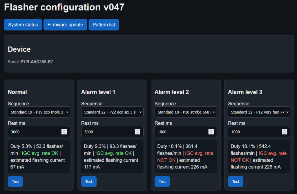
Normal and Alarm Pattern Configuration
This section of the configuration page allows a separate flash pattern to be selected for each operating level:
- Normal — used during normal operation when no FLARM alarm is active;
- Alarm Level 1 — activated automatically when FLARM reports a Level 1 alarm;
- Alarm Level 2 — activated automatically when FLARM reports a Level 2 alarm;
- Alarm Level 3 — activated automatically when FLARM reports a Level 3 alarm.
Each level can use a different pattern and a different rest time. This allows a low-consumption pattern to be used during normal flight and progressively more noticeable patterns to be used for higher FLARM alarm levels.
Sequence
The Sequence list selects the flash pattern used for that operating level.
The available choices include:
- 22 predefined patterns, P1–P22; and
- 4 user-programmable patterns.
The predefined patterns contain different combinations of single, double, triple and multi-flash sequences. User-programmable patterns allow the pulse duration, spacing and number of flashes to be configured separately.
Rest Time
The Rest ms setting defines the pause after the complete flash sequence before the sequence starts again.
The rest time can be adjusted independently for all predefined and user-programmable patterns.
For example, if a selected pattern produces three flashes, the complete operating cycle is:
- the first flash;
- the internal pause;
- the second flash;
- the internal pause;
- the third flash;
- the configured rest time;
- the sequence starts again.
Increasing the rest time:
- reduces the number of flashes per minute;
- reduces the average duty cycle;
- reduces estimated battery consumption;
- reduces average thermal loading.
Reducing the rest time has the opposite effect and causes the sequence to repeat more frequently.
Calculated Pattern Information
The information panel below each level is recalculated automatically whenever the selected sequence or rest time is changed.
It displays:
- the calculated duty cycle;
- the average number of flashes per minute;
- the IGC competition flash-rate indication;
- the estimated average flashing current;
- a high-duty warning where applicable.
Duty Cycle
The Duty value shows the percentage of the complete repeating cycle during which the LEDs are switched on.
The calculation includes:
- all individual light pulses in the sequence;
- the pauses between the pulses;
- the configured rest time after the sequence.
A lower duty cycle normally means lower average battery consumption and lower average heat generation.
Patterns with a duty cycle above approximately 20% are identified as high-duty patterns.
High-Duty Warning
When the calculated duty cycle exceeds approximately 20%, the configuration page displays:
WARNING: HIGH DUTY >20%
This is separate from the IGC flash-rate indication. A pattern can be within the IGC flash-rate range but still have a high duty cycle, or it can be outside the IGC flash-rate range while maintaining a low duty cycle.
High-duty patterns increase average battery consumption and thermal loading. Before testing or saving such a pattern, the controller may ask the user to confirm that the warning has been understood.
The acknowledgement is stored in non-volatile memory so that the controller can remember that the selected high-power configuration has been accepted.
Flashes per Minute
The flashes/min value shows the calculated average number of individual light flashes produced in one minute.
For multi-flash patterns, every individual light pulse is counted as one flash.
For example, one complete triple-flash sequence produces three flashes. The average rate is calculated using the duration of the complete repeating cycle, including the configured rest time.
The displayed value is recalculated immediately when the rest time is changed.
IGC Competition Flash-Rate Indication
The current FAI/IGC Sporting Code Annex A requires competing sailplanes at FAI World and Continental Gliding Championships to have an installed red or white strobe light that is clearly visible to oncoming traffic.
The specified flash rate is:
40 to 100 flashes per minute
This requirement applies to FAI World and Continental Gliding Championships governed by Sporting Code Section 3, Annex A, including the relevant Junior and Women’s championships.
The organisers may also publish additional requirements in the competition Local Procedures. Other competitions may choose to adopt the same requirement, so pilots should always check the rules for the particular event.
The Glider Flasher configuration page automatically compares the calculated average flash rate with the 40–100 flashes-per-minute range.
It displays:
- IGC avg. rate OK — the calculated average rate is between 40 and 100 flashes per minute;
- IGC avg. rate NOT OK — the calculated average rate is below 40 or above 100 flashes per minute.
What “IGC Avg. Rate Not OK” Means
An “IGC avg. rate NOT OK” message does not mean that the pattern is faulty, unsafe or unsuitable for normal flying.
It only means that the calculated average flash rate is outside the specific 40–100 flashes-per-minute range used for the relevant level of FAI/IGC competition.
Patterns outside this competition range are fully valid for normal flying and may be deliberately selected as more noticeable FLARM alarm patterns.
For example, a rapid Level 2 or Level 3 alarm pattern may produce considerably more than 100 flashes per minute. This can provide a strong attention-getting indication during a traffic alert, even though it is outside the average rate specified for the applicable FAI World and Continental Championship rule.
The IGC information is provided specifically to help pilots who take part in competitions where this rule applies. It allows them to adjust the rest time and immediately see whether the selected configuration is within the required average flash-rate range.
Scope of the IGC Check
The displayed IGC indication checks the calculated average flash rate only.
It does not independently confirm:
- the brightness of the completed installation;
- visibility from every viewing angle;
- installation approval;
- compliance with additional Local Procedures;
- acceptance of the installation by competition organisers.
The pilot remains responsible for checking the current rules and Local Procedures for the particular competition.
Estimated Flashing Current
The estimated flashing current value shows the approximate average aircraft-supply current attributable to the selected flashing pattern.
The estimate is based on representative operation from a 13.5 V aircraft electrical supply and the calculated pattern duty cycle.
It is intended to help compare patterns and estimate their relative effect on battery consumption.
The displayed flashing-current estimate does not include all current used by the controller and enabled wireless functions. The complete aircraft current may also include:
- the controller electronics;
- the Wi-Fi access point;
- Wi-Fi UDP FLARM output;
- Bluetooth Classic;
- Bluetooth Low Energy.
Test Button
The Test button temporarily activates the pattern configured for that level.
The test runs for approximately ten seconds and then automatically returns to the pattern required by the current operating state.
This allows the selected sequence and rest time to be checked without permanently forcing the system into that operating level.
When testing a high-duty pattern, an additional warning and confirmation may be displayed.
Recommended Configuration Procedure
- Select the required sequence for Normal operation.
- Set the Normal rest time.
- Check the duty cycle, flashes per minute and estimated current.
- If competition use is intended, check the IGC average-rate indication.
- Use the Test button to examine the selected pattern.
- Repeat the procedure for Alarm Levels 1, 2 and 3.
- Use progressively stronger patterns for higher alarm levels where appropriate.
- Review any high-duty warning before saving the configuration.
- Save the completed settings.
Example Shown
In the example configuration:
- the Normal pattern produces approximately 41 flashes per minute and is inside the IGC competition range;
- the Alarm Level 1, 2 and 3 patterns produce more than 100 flashes per minute and are therefore shown as outside the IGC average-rate range;
- the faster alarm patterns remain suitable for normal non-competition operation;
- the Alarm Level 3 configuration also exceeds 20% duty cycle and therefore displays a separate high-duty warning.
The red IGC message beside the alarm patterns relates only to the competition flash-rate range. The orange high-duty warning is a separate indication relating to average power consumption and thermal loading.
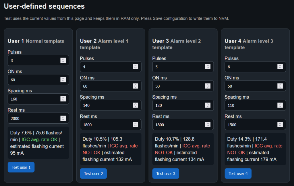
User-Defined Sequences
This section allows four independent custom flash sequences to be created.
The four user-defined sequences are available in addition to the 22 predefined patterns. Any saved user-defined sequence can be selected for Normal operation or any FLARM alarm level. The sequence number does not restrict where the pattern can be used.
Sequence Settings
Each user-defined sequence is configured using four values:
- Pulses — the number of individual flashes in one sequence;
- ON ms — the duration of each flash in milliseconds;
- Spacing ms — the interval between consecutive flashes within the sequence;
- Rest ms — the pause after the final flash before the complete sequence repeats.
Pulses
The Pulses setting determines how many individual flashes are produced in each sequence.
For example:
- 1 pulse creates a single-flash sequence;
- 2 pulses create a double-flash sequence;
- 3 pulses create a triple-flash sequence;
- 6 pulses create a six-flash sequence.
ON Time
The ON ms setting determines how long the LEDs remain illuminated during each individual flash.
The value is entered in milliseconds. For example, an ON time of 60 ms means that every pulse remains active for 0.06 seconds.
Increasing the ON time creates a longer flash and also increases the average power and thermal loading of the sequence.
Pulse Spacing
The Spacing ms setting determines the interval between individual flashes within the same sequence.
A shorter spacing value creates a rapid, closely grouped burst. A longer spacing value makes the individual flashes more clearly separated.
For a three-pulse sequence, operation is:
- first flash;
- configured spacing;
- second flash;
- configured spacing;
- third flash;
- configured rest period;
- the sequence repeats.
Rest Time
The Rest ms setting determines the pause after the final pulse before the sequence starts again.
Increasing the rest time makes the sequence repeat less frequently. Reducing it makes the complete sequence repeat more frequently.
Testing Unsaved Values
The Test user button operates the selected user sequence using the values currently displayed on the page.
The values do not need to be saved before testing. This allows the sequence to be adjusted and tested repeatedly until the required result is achieved.
The test runs for approximately ten seconds and then the flasher returns to the pattern required by its current operating state.
Testing a sequence does not permanently save the displayed values.
Temporary RAM Storage
Values used during testing are held temporarily in RAM.
Temporary values will be lost if:
- the controller is restarted;
- aircraft power is removed;
- the page is reloaded before the configuration is saved.
Saving to Non-Volatile Memory
After the four sequences have been configured, press Save configuration to write them to non-volatile memory.
Once saved, the user-defined sequences remain stored after power is removed and are restored automatically the next time the Glider Flasher starts.
Assigning a User-Defined Sequence
Saving a user-defined sequence does not automatically assign it to an operating level.
After saving, return to the main pattern configuration section and select the required user sequence for:
- Normal operation;
- FLARM Alarm Level 1;
- FLARM Alarm Level 2;
- FLARM Alarm Level 3.
The same user-defined sequence may be assigned to more than one operating level, and any of the four user-defined sequences may be used for any level.
Recommended Configuration Procedure
- Select the required number of pulses.
- Set the duration of each pulse.
- Set the spacing between pulses.
- Set the rest period after the sequence.
- Review the automatically calculated pattern information.
- Press the Test button to check the sequence.
- Adjust and test the values as required.
- Press Save configuration to store the final settings permanently.
- Assign the saved sequence to the required Normal or FLARM alarm level.
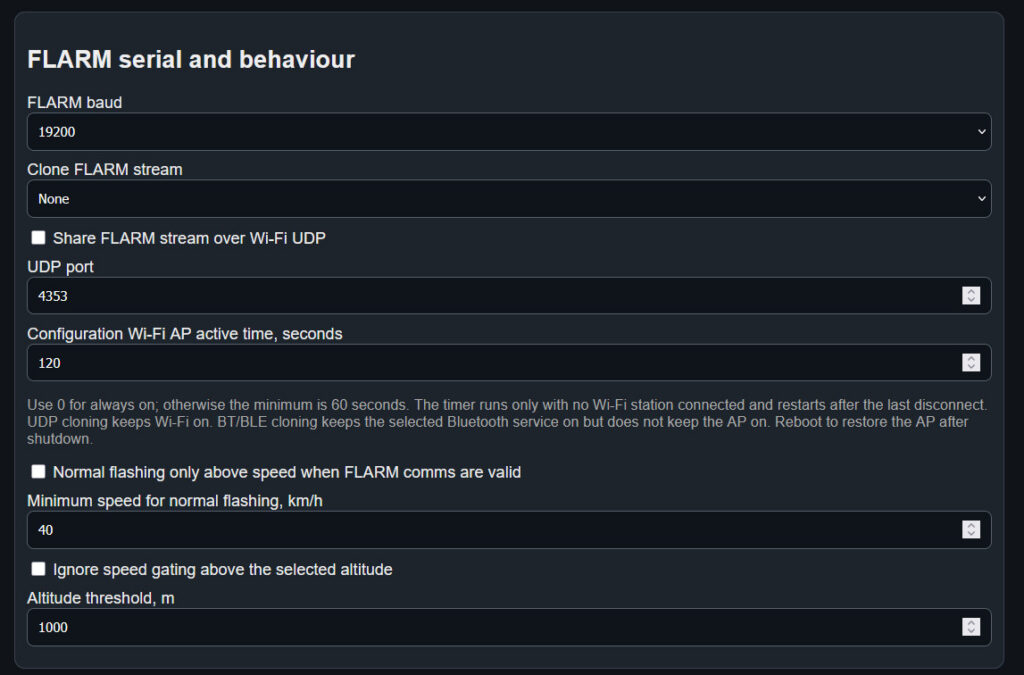
FLARM Serial and Behaviour
This section configures communication with the connected FLARM unit, optional forwarding of the received FLARM data, the configuration Wi-Fi access point and the automatic speed-based flashing control.
FLARM Baud Rate
The FLARM baud setting must match the serial output baud rate configured in the connected FLARM unit. The normal default is 19200 baud.
If the baud rate does not match, the control box will not be able to receive valid FLARM position, speed or alarm information.
Clone FLARM Stream
The received FLARM data stream can be forwarded wirelessly to compatible navigation software or another device.
- None – FLARM data is not forwarded through Bluetooth.
- BT – forwards the stream through Bluetooth Classic.
- BLE – forwards the stream through Bluetooth Low Energy.
- BT and BLE – enables both Bluetooth forwarding methods.
Cloning does not modify the FLARM data. The same received serial stream is forwarded to the selected wireless interface.
Wi-Fi UDP Forwarding
Enable Share FLARM stream over Wi-Fi UDP to forward the received FLARM data through Wi-Fi using UDP.
The UDP port must match the port configured in the receiving application. The default port is 4353.
Configuration Wi-Fi Access Point
Configuration Wi-Fi AP active time controls how long the configuration Wi-Fi network remains available after the last connected device disconnects.
- 0 seconds – the configuration access point remains permanently active.
- 60 seconds or more – the access point closes after the selected period without a connected device.
The timer runs only when no Wi-Fi device is connected. It restarts when the last connected device disconnects.
UDP forwarding keeps the Wi-Fi service operating, but it does not keep the configuration access point permanently available. Bluetooth cloning keeps only the selected Bluetooth service active.
Restoring the Configuration Wi-Fi Network
After the configuration access point has closed, restart the control box to make it available again.
Normal Flashing Speed Control
Enable Normal flashing only above speed when FLARM comms are valid to suppress the normal flashing pattern while the groundspeed reported by FLARM is below the configured minimum.
The Minimum speed for normal flashing is entered in kilometres per hour.
Speed gating applies only while valid FLARM communication and valid speed information are available. It affects the normal flashing mode and does not prevent FLARM alarm patterns from operating.
When a FLARM alarm is received, the flashing pattern assigned to that alarm level is used regardless of the normal-flashing speed threshold.
Altitude Override
Enable Ignore speed gating above the selected altitude when normal flashing should continue at higher altitudes even if the reported groundspeed falls below the configured minimum.
Above the Altitude threshold, the normal flashing pattern is therefore allowed to operate without applying the minimum-speed requirement.
This option is particularly useful during wave flying, where the glider may have a very low groundspeed while still flying at altitude.
Loss of FLARM Communication
Speed gating is used only when the control box is receiving valid FLARM data. If valid FLARM communication is lost, the system returns to the normal flashing mode rather than leaving the flasher suppressed.
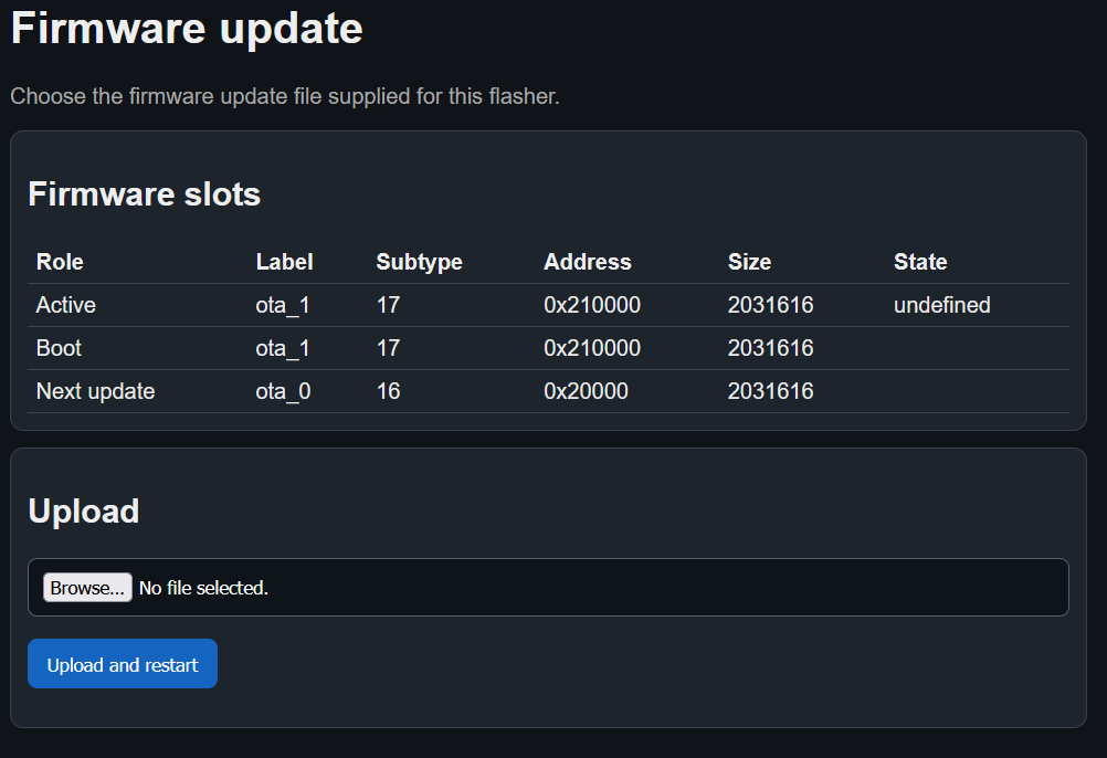
Firmware Update
The Glider Canopy Flasher firmware can be updated wirelessly through the built-in web interface. The controller does not need to be removed from the aircraft, opened or connected to a USB programming cable.
Only install a firmware update file supplied specifically for the Glider Canopy Flasher.
Before Starting
Before beginning an update:
- ensure that the aircraft battery or external power supply is sufficiently charged and stable;
- remain connected to the Glider Canopy Flasher Wi-Fi network;
- do not switch off the controller during the update;
- do not close or reload the browser page while the file is being uploaded;
- use only the supplied Glider Canopy Flasher firmware file.
Firmware Slots
The Firmware slots table displays technical information about the controller’s internal firmware storage.
The controller contains two separate firmware slots:
- one slot containing the firmware currently in use;
- another slot available for the next update.
The roles displayed in the table are:
- Active — the firmware slot currently running;
- Boot — the slot selected for startup;
- Next update — the slot into which the new firmware will be written.
The remaining values, including the slot label, subtype, address and size, are internal technical information. They do not normally provide any useful information for the user and do not need to be changed or interpreted.
State Shown as Undefined
The manual screenshot was taken from a development Glider Canopy Flasher controller on which automatic software-state confirmation was disabled.
For this reason, the State field in the screenshot is shown as undefined. This was expected on that development device and does not indicate a firmware fault or a problem with the update page.
The displayed state may be different in the production firmware.
Selecting the Update File
- Press Browse or Choose file.
- Select the supplied firmware file from the phone, tablet or computer.
- Confirm that the correct filename is displayed beside the file-selection button.
- Press Upload and restart.
The firmware file normally uses the .bin filename extension.
Do not rename, modify or extract the firmware file unless specifically instructed to do so.
Update Progress
After Upload and restart is pressed, a progress bar appears below the button.
The progress bar shows how much of the firmware file has been transferred to the controller. The name of the file being uploaded is also displayed.
During this stage:
- keep the browser page open;
- keep the device connected to the Glider Canopy Flasher Wi-Fi network;
- do not switch off aircraft power;
- do not press the browser Back or Refresh buttons;
- do not start another update.
Automatic Restart
When the upload has completed successfully, the controller stores the firmware in the alternate firmware slot and restarts automatically.
The Wi-Fi connection and browser page may temporarily disconnect during the restart. This is normal.
Allow the controller time to restart, then reconnect to the Glider Canopy Flasher Wi-Fi network if required and open the configuration page again.
After the Update
After reconnecting:
- check the firmware version displayed on the configuration page;
- confirm that the saved configuration is still correct;
- test the Normal pattern;
- check FLARM communication where connected;
- check any enabled Bluetooth, BLE or Wi-Fi UDP outputs.
Normal configuration settings are stored separately from the firmware and should remain available after a routine update.
If the Update Does Not Start
If pressing Upload and restart does not begin the update, check that:
- a firmware file has been selected;
- the selected file is the correct Glider Canopy Flasher firmware file;
- the browser is still connected to the Glider Canopy Flasher Wi-Fi network;
- the controller remains powered;
- the file has not been renamed, altered or corrupted.
Do not repeatedly remove power while an update is being written. Restart the controller and attempt the update again only after confirming that the previous upload is no longer in progress.
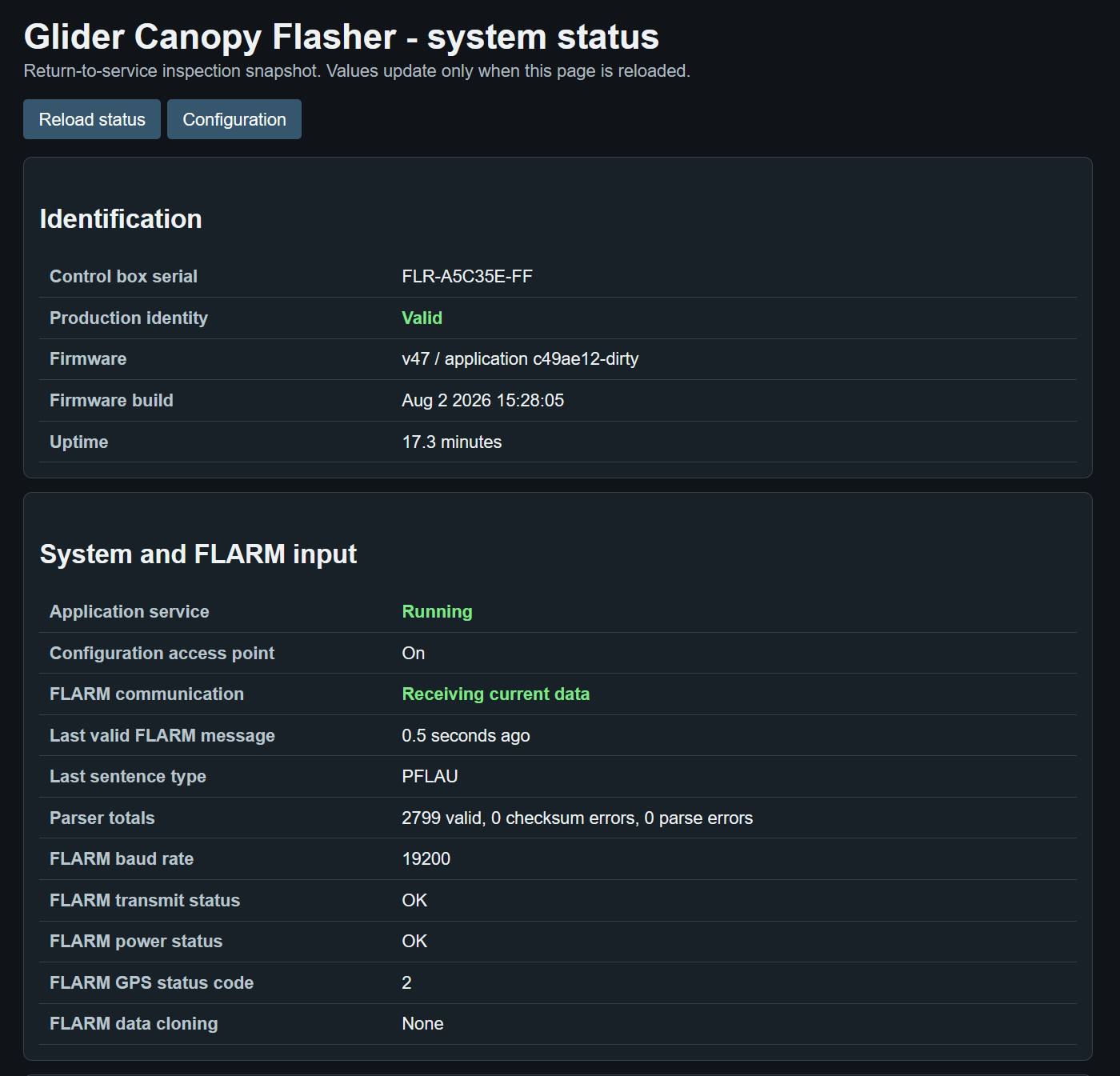
System Status Page
The System Status page provides a read-only snapshot of the control box, FLARM connection and current operating condition. It is intended for installation checks, troubleshooting and return-to-service inspection.
The displayed values are not updated continuously. Select Reload status to obtain a new snapshot. Select Configuration to return to the configuration page.
Status Indications
Green status values indicate that the corresponding function is operating normally. Other values should be checked together with the remaining information on the page before the aircraft is returned to service.
Identification
The Identification section confirms which control box and firmware version are being inspected.
- Control box serial – the unique serial number of the control box. The canopy-mounted flasher head does not have a separate serial number.
- Production identity – confirms whether the programmed production identity and serial-number information are valid.
- Firmware – shows the installed firmware version and application build identifier.
- Firmware build – shows the date and time at which the installed firmware was compiled.
- Uptime – shows how long the control box has been operating since it was last powered on or restarted.
System and FLARM Input
This section confirms that the application is operating and shows the condition of the serial data received from the connected FLARM unit.
- Application service – confirms whether the main control-box application is running.
- Configuration access point – shows whether the configuration Wi-Fi access point is currently available.
- FLARM communication – indicates whether valid and sufficiently recent FLARM data is being received.
- Last valid FLARM message – shows the time elapsed between the most recently received valid FLARM message and the moment at which the status page was loaded.
- Last sentence type – identifies the most recent valid FLARM or NMEA sentence recognised by the control box, for example PFLAU.
- Parser totals – shows the number of valid messages, checksum errors and parsing errors received since startup.
- FLARM baud rate – shows the serial baud rate currently selected in the control-box configuration. It must match the serial output setting of the connected FLARM unit.
- FLARM transmit status – shows the transmitter condition reported by the FLARM unit in its status messages.
- FLARM power status – shows the power-supply condition reported by the FLARM unit.
- FLARM GPS status code – shows the GPS condition code reported by the FLARM unit.
- FLARM data cloning – shows whether the received FLARM stream is currently configured to be forwarded through Bluetooth, Bluetooth Low Energy or both.
Checking the FLARM Connection
During a normal connection check, the page should show Application service: Running and FLARM communication: Receiving current data. The age of the last valid FLARM message should remain low each time the page is reloaded, and the number of valid parser messages should increase.
Communication Errors
A small number of errors may occur while connecting or disconnecting equipment. Continuously increasing checksum or parsing errors can indicate an incorrect baud rate, damaged cable, poor connection, electrical interference or an incompatible serial-data format.
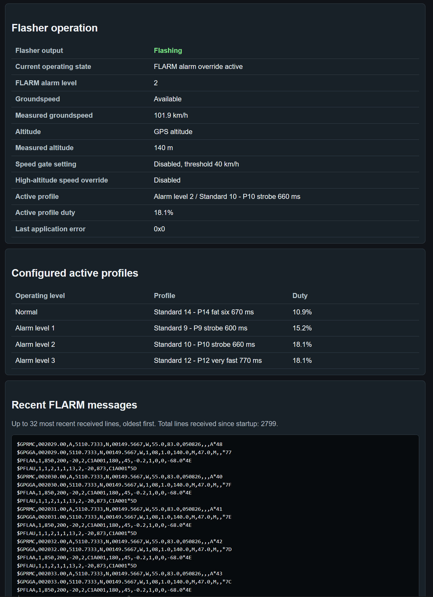
Flasher Operation
The Flasher operation section shows the current operating condition of the canopy flasher and explains why a particular flashing profile is active.
- Flasher output – shows whether the flasher output is currently flashing or inactive.
- Current operating state – identifies the condition currently controlling the flasher. This may be normal operation, speed gating, a FLARM alarm override or another system state.
- FLARM alarm level – shows the alarm level currently reported by FLARM. Alarm level 0 means that no collision alarm is active. Alarm levels 1, 2 and 3 select their corresponding configured flashing profiles.
- Groundspeed – confirms whether valid groundspeed information is currently available from the received FLARM data.
- Measured groundspeed – shows the most recently received valid groundspeed in kilometres per hour.
- Altitude – identifies the altitude source currently being used, such as barometric altitude or GPS altitude.
- Measured altitude – shows the most recently received valid altitude in metres.
- Speed gate setting – shows whether normal-flashing speed gating is enabled and displays the configured groundspeed threshold. When disabled, the stored threshold is shown but does not suppress normal flashing.
- High-altitude speed override – shows whether the altitude-based override of speed gating is enabled. When active above the configured altitude, normal flashing is permitted even if the measured groundspeed is below the speed threshold.
- Active profile – identifies the operating level and flashing profile currently controlling the flasher.
- Active profile duty – shows the percentage of time for which the LEDs are switched on within the complete repeating profile. This value is useful when checking the thermal loading and average power consumption of the selected pattern.
- Last application error – shows the most recent internal application error code. A value of 0x0 means that no application error has been recorded.
Understanding the Current Operating State
FLARM alarm operation takes priority over the normal flashing profile and the normal-flashing speed gate. For example, when FLARM alarm override active is displayed, the profile assigned to the reported FLARM alarm level is controlling the flasher.
The displayed groundspeed, altitude and gating settings make it possible to confirm why the normal profile is active or suppressed and whether an altitude override is affecting the decision.
Configured Active Profiles
The Configured active profiles table shows the flashing profile assigned to each operating level.
- Normal – the profile used during normal operation when no FLARM collision alarm is active.
- Alarm level 1 – the profile used for a FLARM level 1 alarm.
- Alarm level 2 – the profile used for a FLARM level 2 alarm.
- Alarm level 3 – the profile used for a FLARM level 3 alarm.
The Profile column shows the name of the profile assigned to each level. The Duty column shows the LED on-time as a percentage of the complete repeating pattern.
This table allows the selected configuration to be checked without activating each alarm level. It does not replace the normal visual power-on test of the flasher output.
Recent FLARM Messages
The Recent FLARM messages section displays the most recent raw serial-data lines received from the connected FLARM unit.
Up to 32 messages are shown, with the oldest displayed first. The total number of received lines since startup is shown above the message window.
Depending on the connected FLARM configuration, the displayed data can include:
- GPRMC – navigation data including time, position, groundspeed and course.
- GPGGA – GPS fix, position and altitude information.
- PFLAA – relative information about detected aircraft or other FLARM targets.
- PFLAU – FLARM operating status and collision-alarm information.
This information is intended primarily for installation checks and troubleshooting. It can be used to confirm that the expected sentence types are being received and that FLARM alarm messages reach the control box.
Each valid sentence normally ends with a checksum following the * character. Checksum and parsing results are summarised separately in the System and FLARM input section.
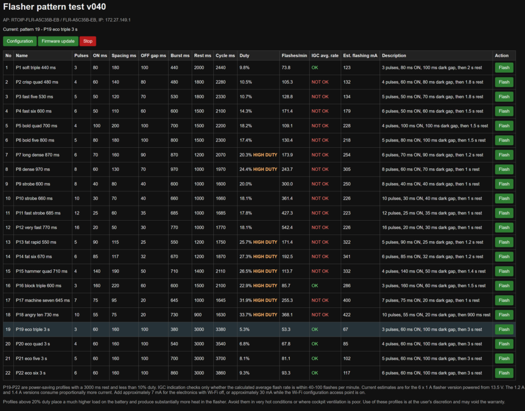
Standard Pattern List and Test
Pressing the Pattern list button on the main configuration page opens the complete list of the 22 predefined Glider Canopy Flasher patterns.
This page allows the user to:
- review the timing and operating characteristics of every predefined pattern;
- compare duty cycle, flash rate and estimated consumption;
- identify lower-consumption and high-duty patterns;
- test any predefined pattern directly.
The predefined pattern parameters cannot be edited on this page. When a pattern is assigned to Normal operation or a FLARM alarm level, its Rest ms value can be adjusted separately on the main configuration page.
Current Pattern
The line beginning with Current shows the pattern that is currently operating.
The corresponding row in the table is also highlighted, making it easy to identify the active pattern.
Wi-Fi Information
The information near the top of the page identifies:
- the Glider Canopy Flasher Wi-Fi access-point name;
- the unit identifier or serial number;
- the local IP address used to access the web interface.
Pattern Table
Each row represents one of the 22 predefined patterns, P1–P22.
No
The No column shows the numerical position of the pattern in the list.
Name
The Name column shows the pattern number and a short descriptive name.
Examples include:
- soft triple;
- crisp quad;
- fast strobe;
- block triple;
- ECO triple.
The name gives a general indication of the visual character of the pattern.
Pulses
The Pulses column shows how many individual flashes are produced during one complete burst.
For example, a triple pattern contains three flashes, while a ten-pulse pattern contains ten flashes.
ON ms
The ON ms column shows how long each individual flash remains illuminated.
The value is shown in milliseconds.
Spacing ms
The Spacing ms column shows the interval from the beginning of one flash to the beginning of the next flash within the same burst.
This value includes both the LED ON time and the following dark interval.
OFF Gap ms
The OFF gap ms column shows the actual dark period between the end of one flash and the beginning of the next flash.
It is calculated from the pulse spacing minus the LED ON time.
Burst ms
The Burst ms column shows the total duration of the grouped flash burst, measured from the beginning of the first pulse to the end of the final pulse.
It does not include the longer rest period after the burst.
Rest ms
The Rest ms column shows the default pause after the final flash before the complete pattern repeats.
When the pattern is selected on the main configuration page, this rest time can be adjusted independently for Normal operation and each FLARM alarm level.
Cycle ms
The Cycle ms column shows the duration of one complete repeating cycle.
It includes:
- the complete flash burst;
- the rest period following the burst.
Duty
The Duty column shows the percentage of the complete cycle during which the LEDs are illuminated.
Patterns above approximately 20% duty are marked HIGH DUTY.
High-duty patterns produce greater average battery consumption and greater thermal loading. They are primarily intended for short-duration or special-purpose use.
Flashes per Minute
The Flashes/min column shows the average number of individual light flashes produced during one minute.
Each individual pulse within a multi-pulse burst is counted as one flash.
IGC Average Rate
The IGC avg. rate column compares the calculated flash rate with the 40–100 flashes-per-minute range applicable to the relevant FAI/IGC competition requirement.
- OK means the average flash rate is within that range.
- NOT OK means the average flash rate is below 40 or above 100 flashes per minute.
An IGC NOT OK indication does not mean that the pattern is faulty or unsuitable for normal flying. It only means that its average flash rate is outside that specific competition range.
Estimated Flashing Current
The Est. flashing mA column shows the estimated average aircraft-supply current used by the flashing pattern.
The displayed estimate is based on the standard six-LED, 1 A Glider Canopy Flasher version operating from a representative 13.5 V aircraft supply.
The estimate is intended mainly for comparing the relative battery consumption of different patterns.
Description
The Description column provides a plain-language summary of the pattern timing.
It shows:
- the number of pulses;
- the ON duration of each pulse;
- the dark gap between pulses;
- the default rest period after the burst.
Flash Button
The Flash button in the Action column temporarily tests the corresponding predefined pattern.
The test uses the timing values shown in that row and operates for approximately ten seconds. The controller then returns to the pattern required by its current operating state.
Testing a pattern from this page does not change the saved Normal or FLARM alarm assignments.
Configuration Button
The Configuration button returns to the main Glider Canopy Flasher configuration page.
Use the main configuration page to:
- assign patterns to Normal operation and FLARM alarm levels;
- adjust the rest time;
- configure user-defined sequences;
- save settings to non-volatile memory.
Firmware Update Button
The Firmware update button opens the wireless firmware-update page.
Stop Button
The Stop button immediately stops the LED output. It is intended for ground testing, inspection or situations where the light output needs to be stopped quickly.
ECO Patterns
Patterns P19–P22 are lower-consumption ECO patterns.
They use a longer default rest period of approximately three seconds and remain below approximately 10% duty cycle.
These patterns are intended for normal operation where lower average battery consumption is preferred.
Selecting a Pattern
The Pattern List page is used for reviewing and testing the predefined patterns. It does not assign the selected pattern permanently.
To use a pattern:
- review or test the required pattern on this page;
- press Configuration;
- select the pattern for Normal operation or the required FLARM alarm level;
- adjust the rest time where required;
- press Save configuration.
After Configuration
Press Save configuration before leaving the configuration page if any settings have been changed.
When configuration is complete, the phone or computer can be disconnected from the flasher network and reconnected to its usual Wi-Fi network.